

Build record · Electronics panel
Plan the panel.
Then check the fit.
Waggy needs a place for its power supplies, motor driver and computer. This case study follows how Fyrwake turns that problem into a layout, a paper template and a connection drawing the builder can review.
Demo project · simulated readings. Physical verification remains pending.
The starting point
One panel, several constraints.
Waggy is a yard-robot project built around a garden cart, wheelchair drive and front lawn sweeper. The electronics need to fit inside that machine while leaving room to reach terminals, route wires and service components.
The available record contains an app layout, a generated marking template and wiring views. The task is to carry the same parts and decisions through all three, then check them against the real components.
- Project
- Waggy yard robot
- Subsystem
- Electronics panel
- Outputs
- Layout, marking PDF, connection detail
- Next evidence
- Measured parts and a physical fit check
Layout
Give each component a place.
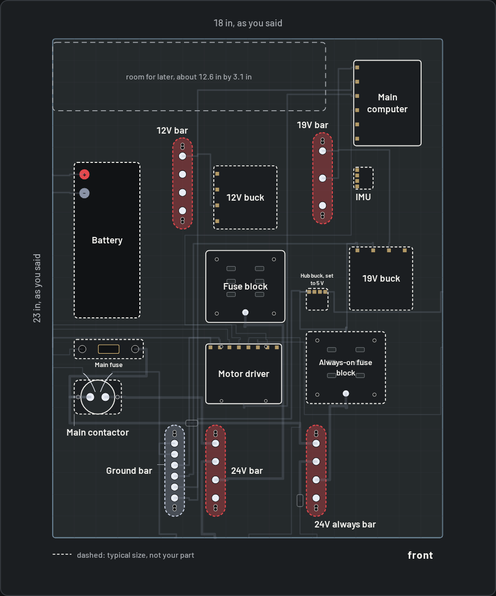
The app drawing brings the battery, motor driver, fuse blocks, voltage converters and main computer onto one panel. It also shows distribution bars and space reserved for later additions.
This makes the arrangement reviewable: can the builder reach a terminal, remove a part and route its wires? A component fitting inside a rectangle does not establish that its connectors, cooling or mounting holes will fit.
The drawing marks provisional component sizes with dashed outlines. Those outlines are useful planning inputs; the next step is to replace assumptions with measurements.
Paper fit
Take the drawing to the bench.
The generated PDF contains 14 pages, including a panel template split across eight paper tiles. It includes a four-inch scale check so the builder can check the print size before placing components on the paper.
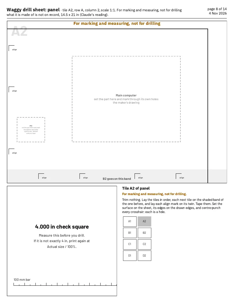
A fit check, before a mounting decision.
Use the real component and its own mounting holes to check the proposed position. The export is a marking aid; it is not a verified drilling pattern.
Open the original 14-page PDF →For marking only · not for drillingConnections
Follow one connection at a time.
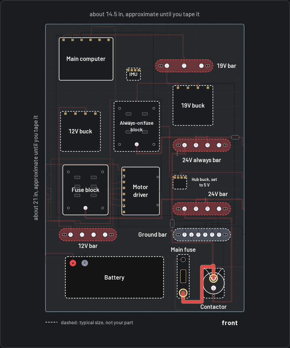
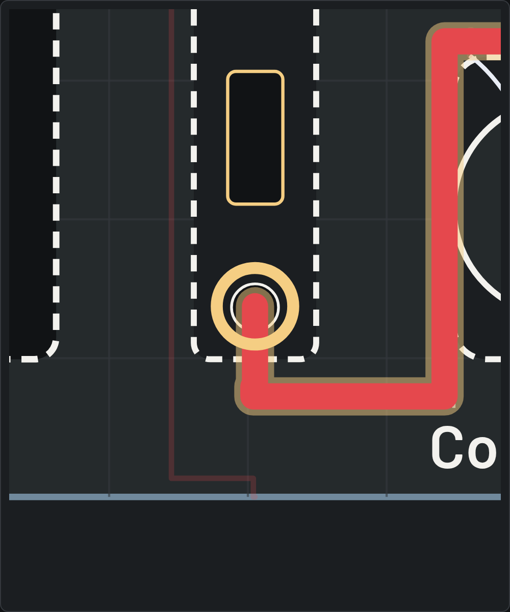
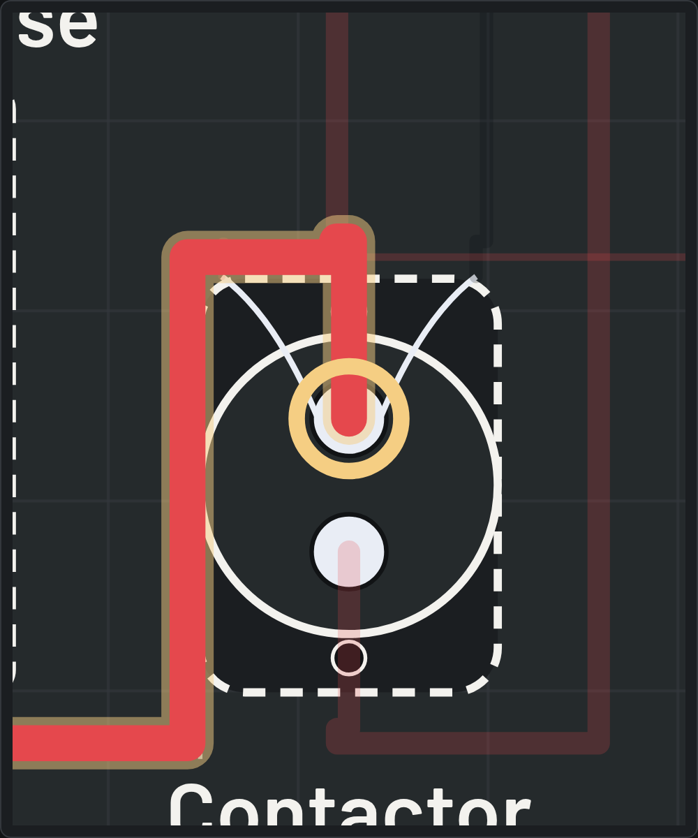
The wiring view highlights a connection and dims the surrounding wires. Separate close-ups show its starting point and destination, so the builder can inspect both ends without losing the wider layout.
The separate decision-review captures on the homepage show a proposed electrical change, a parts list, a build instruction and an unresolved check. They demonstrate the app’s review workflow using demo data; they do not establish that this physical panel has passed a test.
Inspect the decision-review captures →Evidence & next checks
What this record establishes.
Available to inspect
- A component layout with provisional dimensions identified.
- A printable marking template with a scale check.
- A highlighted connection and views of both terminals.
- App captures of review, parts, build steps and an open check.
Still needs evidence
- One measured panel size shared by the layout and PDF.
- Actual component dimensions, mounting positions and access.
- A dated photo of the physical fit check and any corrections.
- Recorded checks of the assembled panel against its reviewed design.
The demonstrated result is a set of outputs that can be inspected and compared. No build-time saving, successful power-up or completed yard trial is claimed in this record.
Bring your project
Have a subsystem to work through?
Start with your files, parts and the decision you need to make.